

Business documents, including business forms, are designed by humans for humans. The design and layout uses visual conventions and constructs developed since the dawn of printed materials. This fact, coupled with the fact that we grow up reading and filling in business documents, means that a person can normally understand how to read or use most business forms with relative ease. Including forms we haven’t seen before.
However, now we want machines to read these forms as well. The problem is that machines do not understand the visual conventions and constructs; it simply sees black dots on white background. We have developed computer software to mimic how humans understand forms, though without human intuition and experience a machine process can simply apply logic that depends on consistency and repeatability. And the specific logic applied to read forms must often be dictated on a form-by-form basis.
Designing a business form to be well suited to machine processing would create a sterile, hard-to-understand layout that is the opposite of what is desired for human usage of the form. This means that making business forms useable by both humans and machines is a matter of compromise, and balance between what is most effective for one vs. the other.
This document provides guidance as to how to modify business documents to be more “machine friendly” while assuming that the balance will remain predominantly skewed toward human-readability.
Recognition phase of capture is the most important step, the phase where OCR is performed. The accuracy of OCR is greatly affected by the design of the form. In general, clean images of a standard size with clearly written characters are best for OCR. Extra time and consideration spent in forms design will pay strong dividends in recognition accuracy and reduced costs for many data entry.
So how can we get the best optical character recognition (OCR) and indexing possible? This article provides recommendations regarding how we should address automated indexing during document capture.
Typical form layout features needs to be machine-friendly:
• Form identification
• Form data location layout
• Overall form text attributes
• Anchor Marks for alignment correction
What we need to avoid in form layouts to increase machine-readability:
• Shaded or watermarked areas surrounding printed data to be read
• Positional variation for data elements to be read automatically
• Using color text within context (i.e. text of different color means different things)
• Small or unusual fonts for data elements to be read automatically
Form Identification
A human looking at a business form can quickly scan the form top-to-bottom in seconds and we pick up enough visual cues and keywords to determine the kind of form. This technique COULD be applied to teaching a machine to identify a form, however:
• The form-identification logic to be applied must be determined beforehand and therefore must be predictable. Humans can read a form multiple times, varying the techniques we apply until the form make sense. Machines can be taught to mimic this to a point, however the logic it can apply will always be limited to a finite set of pre-determined techniques.
• Machines can’t apply human intuition – the form identification logic must pass or fail (it IS a specific form or it is not).
• Humans use intuition when reading text and we automatically correct text-reading mistakes. ON first glance if we read “Form 1194 rev1sion A”, we automatically correct ourselves that the text was supposed to be “Form 1194 revision A”. The machine reads it as “Form 1194 rev1sion A”; and that’s it.
Why do we need to identify exactly the form type? Because machine processing of a form depends on the application of the correct data location and business logic specifically for that form. Applying the incorrect data location and business logic yields (at best) useless results and (at worse) yields incorrect results without knowing the results ARE incorrect.
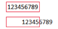
Consider the simple case of “Form 1194 revision A” and “Form 1194 revision B”. These two revisions of the same form are nearly identical, however to make room for an additional company contact fixed text element the data element “Claim number” was moved to the right 1/2”. To a human reading the form, this makes almost no difference in the accuracy of locating the claim number. However to a machine process expecting the claim number to be in a specific location, the difference between “revision A” and “revision B” is claim numbers “123456789” and “12345”.
This simple example illustrates how misidentifying even the revision # of the same form during form identification can foul up the entire process.
Another example of why we need to identify exactly the form type involves automated form processing.
Typically, document processing proceeds in this way:
1. Page Ingestion (scanning or reading page images from some source)
2. Page Identification
3. Automated Data Location and Validation
4. Data Correction (human user interface interaction)
5. Export to Business Systems
For this example assume that a “Form 1194” processing involves locating and validating 10 data elements, and “Form 1050” processing involves locating and validating 14 different data elements. What will happen if a 1194 form was misidentified as a 1050? The machine will have applied the “Automated Data Location and Validation” logic for a 1050 which is completely inappropriate to an 1194. When the form gets to the “Data Correction” task the information presented to the user will be completely wrong and therefore the opportunity to save time and increase accuracy through automation will be lost.
The bottom line is that for any kind of automated document processing to work every form must be identified correctly early in the processing workflow. This identification can be manual or using predetermined automation rules, backed up by manual identification as required.
The various techniques and options available to perform automated form identification is beyond the scope of this document, however form design guidelines that will make automated form identification more accurate include:
1. Including machine-oriented form identification markers such as:
a. Barcode – including form number AND revision
b. Form identifying text printed in at least 12-point font in clear whitespace at least 1/2” from all page borders. Note that identification accuracy using text for form identification depends on successful and accurate Optical Character Recognition (OCR) which depends on the print quality AND scan quality.
2. Text keyword(s) found on a form that is guaranteed to be unique to the specific form. Note that this technique requires applying OCR to a larger area of the form and is therefore slower, and it depends on consistent OCR accuracy.
One critical note regarding the use of Datacap Fingerprint features for form identification. These features were developed for a specific usage and is only suited for differentiating the same type of form (i.e. invoice) across many different layouts (i.e. different vendors or suppliers). It does NOT suited for identifying similar business forms of different types (i.e. Form 1194 vs. 1050) because it can be easily fooled by similar layouts. This is because these features relay on graphical-only processing and therefore depend on different header graphics and fixed header area layout differences typical of forms from different sources. While Datacap Fingerprint features excel in what they are designed to do, they must be applied only in in applicable form identification scenarios.
Keep in mind the on-going cost of maintaining automated form identification logic as compared to investing in the most efficient and effective form design. Modifying the document processing application to associate a new barcode value to a new form design is significantly easier and lower risk than changing text keyword logic.
Form Data Location
Datacap provide many features and techniques to locate individual data elements on the page. The most common and effective techniques are:
1. Positional – the data element is found in exactly the same location on the page every time
2. Keyword Located – the desired data element is found adjacent to a keyword
Positional
A “template” of data locations is created for each form. The form identification task success selects which of these templates is applied to any given form.
The critical form design guideline for positional data location is consistent location across all printing methods and form ingestion methods.
For example, if not pre-printed for distribution, the printer used will vary the exact size of the page which in turn affects the data location when ingested. When possible for non-preprinted forms, distribute as PDF as this reduces resizing differences to the extent possible as compared to distributing as word processing file or image file formats.
When the form is ingested via scanning, the location of the data on the page will also vary somewhat because of mechanical feeding into the scanner. If the ingestion is from a file this variation is eliminated.
The ingestion resolution (DPI – dots per inch) must match the form template for which it was designed. In other words, a template designed at 300 DPI will not work correctly if the form is ingested at 200 DPI.
Datacap will attempt to correct some page alignment variations by comparing the form template, however what it can do in this regard is limited without solid reference points on which to base the alignment corrections. If the form contains any data location that requires a high degree of alignment accuracy, such as checkboxes, the form must include “Anchor Marks”. See the section of this document describing Anchor Marks.
Keyword Located
This data location technique depends on finding a predicable keyword such as “Invoice Number:” then looks immediately to the right, left, above or below for the actual value.
That means that the from design guidelines for keywords are a) predictable keywords, b) clear-reading text in decent font style and size, c) exact horizontal alignment of the keyword and the desired data value (if to the right or left of the keyword).
Keyword location is not adversely affected by page alignment variations such as described in Positional location, however it IS directly affected by the consistent effectiveness of OCR.
Overall Form Text Attributes
Typically the full body of text on the page images is read using OCR at some point in processing. To optimize the success and accuracy of OCR, the form design should include:
• Text should be no less than 10 point font
• Text should be a “standard” business font and not a highly-stylized font
• Text should be on a white background, not shaded or watermarked
Of course, text on the form that does not matter if it is successfully read via OCR (i.e. user instructions or corporate branding/advertising) can be in any style and on any background.
Anchor Marks
Printers and document scanners are mechanical devices that draw paper through with rollers and feed guides. That means that the printing on the page will not always be exactly in the same place on the page, and the scanned image of the page will likewise not be exactly consistent. The page will sometimes be skewed (crooked) as it is drawn through scanner. The page image can actually “stretch” slightly compared to the original due to sheet feeding.
Datacap includes features to attempt to automatically correct page alignment and stretching. For these features to work best Datacap needs something graphical on the page on which to base this correction. The best solution are known as Anchor Marks.
Anchor Marks are small, unobtrusive geometric shapes printed on the form. Anchor Marks should be solid (filled) geometric shapes with crisp edges with sharp corners so that alignment is possible “to the pixel”.
Text characters CAN be used as Anchor marks, however, they do not always have consistently crisp enough edges to match effectively.
Note that if the form includes data location that is highly location dependent, such as checkboxes, anchor marks are absolutely necessary. One anchor mark is good, however two anchor marks should be considered to be required if checkbox detection will be done on the form. Dual anchor marks allows Datacap to correct page offset, stretching, and “skewed” (crooked) page images.
While top and bottom are most effective, they can be located anywhere on the page. Opposite corners diagonally is best.
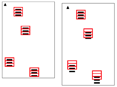
The following illustrates how page image “stretch” compensation is achieved. The red zones are where data elements are expected to be on the page for a specific form. The triangle anchor mark at the top-left of the form allows Datacap to adjust the page offset, however note how the zones near the bottom of the page no longer line up with the data elements? This is because of page stretch (this illustration is a bit exaggerated to make a point).
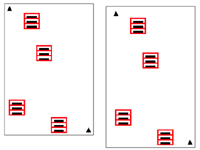
However, if top and bottom Anchor Marks are employed, the Datacap “offset” mechanism will automatically reposition zones in a way that accounts for page stretch or skew; to the degree possible.
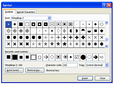
To generate Anchor Marks, the easiest way is font type “Wingdings” and font size 10.
Note: A variety of Windings characters can be used but do not use the hollow characters – only solid filled, geometric shape characters should be used.
Always place the anchor at least ½” from the edges of the page, even if there is unused form space.
Shading and Watermarks
Shading or color backgrounds are often applied within a form design for aesthetic appeal or to provide context to assist in understating the form.
Unfortunately, shading and color backgrounds significantly and negatively affect a machine attempting to read text from the form.
The way OCR works involves looking at every dark dot on the page image in conjunction with all nearby dark dots on the page to compare against the pattern of all known text characters. When the text character images are crisp, dark patterns on a clean white background, OCR is quite accurate. However, what do you think happens when the OCR engine encounters this?
Shading is the enemy of edge detection, therefore the OCR engine will not have much luck with the above. And shading comes in many forms. When a colored background is converted to black and white for OCR execution, the color fill is often converted to a shaded area.
For purposes of this discussion, watermarking is another form of shading. Often watermarking is employed on a form to specifically make it apparent that a form has been copied or scanned as a fraud detection technique. Watermark patterns for this purpose are specifically selected for maximum visual distortion when copied or scanned. As such, OCR results on form areas covered by watermark patterns is generally poor.
Color Text
OCR engines look at black dots on white background. Therefore scanned page images are automatically converted to monochrome (black and white) before the OCR processing.
Conversion of the scanned page image from color or grayscale to monochrome may reduce clarity as the process can result in “dithering”.
The following TIF image snippets are from a clean, color-scanned TIF. The snippet on the left is 24-bit color, and on the right converted to monochrome which is required by the recognition engines. They are shown at 225% magnification.
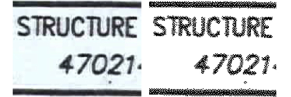
Therefore, it is must be understood that scanning in color can have adverse effects on OCR effectiveness and accuracy which should be considered from a business standpoint.
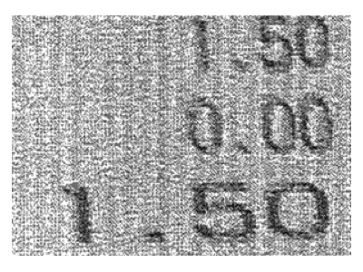
This also means that if the color of text is important, the fact that it is in color is lost during the processing. A good example is a positive number in black whereas a negative number is printed in red.
Barcode Tips
Barcode types fall into the categories of one- and two-dimensional barcodes. One-dimensional barcodes (traditional) are a series of parallel lines. These are accurate even in relatively bad image quality because of their simplicity. However these barcodes can’t include very much data without getting large in size and therefore using up considerable real estate on the form.
On the other hand, two-dimensional barcodes employ various scatter-patterns of marks instead of, or as supplement to, the traditional parallel lines. These barcode types can carry a larger amount of data in a relatively small footprint HOWEVER they can be rendered unreadable by image quality relatively quickly.
The best example of quality-vs.-readability involves a faxed form page. The likelihood of a one-dimensional barcode remaining readable is high from a faxed page, as compared to a two-dimensional barcode which will rarely be readable from a faxed page.
Because barcodes rely on the positon and percentage of “dark mark width” vs. “white space”, be sure to leave a “guard band” of white space on all sides of a barcode that is at least 3 times wider that the widest white space found in the barcode itself.
When possible choose a barcode format that includes a “check sum” value so the barcode reading engine can automatically tell the difference between a good read and a bad. If not using a check sum, consider formatting the data to be encoded into the barcode in such a way that the application itself can discern between a valid barcode read and not.
Experiment with different barcode placement and sizes to identify the best compromise between the page real estate used by the barcode and reading effectiveness. Invest the time to get this right to yield the most benefits from barcoding your forms.
Check Boxes
Checkbox detection requires a significant effort in establishing a threshold or percentage of dark pixels inside the check box. Checkboxes can be created with dotted-lines as well to assist in drop out/image cleanup for empty check boxes. This will also assist threshold detection. Try to keep all checkboxes as consistent within a document as possible.
- Leave sufficient space for legibility and unambiguous check box selection, providing at least
- 5 mm between check box and label / instructions
- 3 mm between check boxes
- Maintain a consistent size of checkboxes within a document.
- Users are more inclined to shade circle check boxes and tick square check boxes. Therefore, if check box detection is to be applied to the form, use circle check boxes instead of square ones because shaded circle check boxes will yield higher pixel count leading to higher success rate for check box detection.
- However, if the form is to be converted to PDF format for electronic form filling, use square check boxes instead as the reverse is true. PDF will provide a higher pixel count for square check boxes of the same length/diameter